Sanitation District in Kentucky Faces Challenge Head-On
Sanitation District No.1 (SD1) of Northern Kentucky is the second largest public sewer utility in Kentucky with a service area that covers approximately 220 square miles. It is responsible for the collection and treatment of northern Kentucky's wastewater, as well as regional storm water management.
- By Erin Boudreaux
- May 17, 2013
SD1 encompasses more than 30 municipalities and unincorporated portions of Boone, Campbell, and Kenton Counties. The district maintains more than 1,700 miles of sanitary sewer line, 142 wastewater pumping stations, 15 flood pump stations, eight package treatment plants, three major wastewater treatment plants, more than 400 miles of storm sewer, and over 30,000 storm sewer structures.
Deep Tunnel Addresses Issues
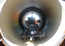
A recently completed project by SD1 was the Western Regional Conveyance Tunnel (WRCT) located in Boone County, Ky. This $110 million project was undertaken in order to effectively serve a booming population while complying with a consent decree addressing sanitary sewer overflows and combined sewer overflows concerns in Boone County and parts of Kenton County. To date, the WRCT is the largest capital project in SD1's history. The WRCT system is a gravity sewer project that routes flow to the new Western Regional Water Reclamation Facility, which has a treatment capacity of about 20 million gallons a day of wastewater.
The tunnel project consisted of 32,610 feet of 8.5-foot diameter pipe installed by tunneling methods, 2,900 feet of pipe installed by open cut sewer installation, and a 700-foot pipe bridge over Willoughby Creek. The tunnel was bored through shale and limestone and runs from central Boone County near Camp Ernst Road west to Route 20 near the Ohio River. Both the tunnel and Western Regional Water Reclamation Facility are projected to reduce sanitary sewer overflow volumes by 59.7 million gallons annually and will eliminate 14 older pump stations.
Eliminating pump stations will increase efficiency and reduce facility maintenance costs. The WRCT tunnel provides 14 million gallons of wet-weather storage and creates system capacity for future growth.
The completed sewage tunnel was recently recognized as Environmental Initiative of the Year by New Civil Engineer magazine, a European trade publication.
The Tunnel Design and Construction Management Team included HDR Quest, Hatch Mott MacDonald, AECOM, CH2M Hill, and Thelen Associates. McNally Kiewit, a joint venture, won the bid as general contractor.
Corrosion Resistant Shafts
There are five shafts located along the length of the project ranging in diameter from 16 to 51 feet with depths ranging from 55 to 300 feet. Shaft number 1 is a vortex drop structure that conveys flow from the surface to the tunnel. Shafts 2, 3, and 4 are maintenance access shafts. Shaft 5 houses gates, flow-measuring devices, and other equipment. Centrifugally cast, fiberglass reinforced, polymer mortar (CCFRPM) pipe with a stiffness class of 350 pounds per square inch (psi), manufactured by Hobas Pipe USA was vertically installed in the shafts. It included both 640- of 85-inch diameters and 109 feet of 66-inch diameter pipe.
On some deep sewer tunnel projects, corrosion resistance is a major concern as acids produced in the sewer can attack and corrode the concrete lining. This was the case for the WRCT. In addition to the need for corrosion resistant pipe, the WRCT tunnel was also under as much as 130 psi of external water head. These kinds of pressures can de-bond thin, impermeable membranes if measures are not taken to release the pressure. For the WRCT project, officials specified a pipe for the shaft linings that would remain corrosion resistant and stand up to a 130 psi of external water head plus 50 psi of additional rock pressure.
As a prequalification, pipe manufacturers were required to prove the pipe and joint system were capable of meeting the external pressure design conditions. Hobas Pipe USA, along with Plug-It, designed and built a custom joint tester that can verify the external capability of an assembled pipe joint.
Not Your Average Tunnel Project
Three thousand feet of 102-inch CCFRPM pipe was installed by open cut, with a small quantity of pipe installed in jacked casing below Route 20. Two hundred forty feet of 72-inch CCFRPM pipe was installed in jacked casing below Camp Ernst Road.
An important aspect of this project was the 700 foot pipe bridge that crosses Willoughby Creek. To keep construction time and effort at a minimum and maintain straight alignment, the tunnel would have had to “daylight” at Willoughby Creek or cross beneath the creek as a siphon. Maintenance reasons caused the project engineers not to design a siphon at the creek crossing and instead designed an aerial pipe bridge.
Michael Vitale, P.E., senior vice president, Hatch Mott MacDonald explained, “The only other option for the creek crossing would have been an inverted siphon below grade. However, since siphons can fill and plug, requiring costly maintenance, SD1 preferred the aerial bridge. The bridge allowed for the entire seven mile sewer to flow by gravity with no pumps or siphons.” The bridge was at grade at each abutment and 30 feet above ground at the highest point.
This aerial bridge, located downstream of shaft 5, was designed with CCFRPM. “Hobas was selected primarily for its lower weight. This led to less load; hence, less foundation and substructure. It also provided corrosion resistance, which was a project requirement,” stated Vitale. In addition, this pipe material is UV resistant.
Overcoming Challenges
“One of the challenges in the design of the bridge was the differential thermal expansion between the steel bridge and the pipe material, but this was dealt with during design. Each pipe joint was anchored on the bridge with straps, and a special expansion section was installed at one end of the bridge to take up any movement,” explained Vitale.
The expansion and contraction of the bridge due to thermal changes was accommodated at one end with the expansion section. Hobas provided two flanged ends to connect to the expansion section designed by the project engineering team. The pipe thermal change was accommodated at every joint along the 700 feet. A 100 degree temperature change would result in three-eighths of an inch growth or shrinkage in a 20-foot section. Each joint can accommodate one-inch of movement, so the Hobas FWC couplings not only provided a leak-free connection, but also served as expansion joints for the pipe.
“The utilization of Hobas pipe across the aerial bridge allowed the bridge to be built more economically by reducing the load requirements, which in turn allowed for less foundation and support structure. It also provided inherent corrosion protection which was very important to us,” stated Christopher Novak, deputy executive director of operations, SD1.
With the support bridge fabricated, it took McNally-Kiewit two weeks to install and test the pipe. “Each joint was air-tested at five psi and held for roughly one minute,” explained Gary Bulla, project manager, McNally Kiewit. All joints passed the test and were leak-free.
The tunnel has been in operation since April of 2012 and all sections have been performing well. This was a new installation for Hobas and all others involved. Through joint effort, a solution was designed and successfully installed. “The aerial pipe bridge has performed extremely well for us since it was put in service. The installation of the Hobas pipe across the bridge went flawlessly. There is no question in my mind that using Hobas pipe in this situation was certainly the right decision,” explained Novak.
For more information, please click here.
About the Author
Erin Boudreaux is a marketing manager at HOBAS Pipe USA. She earned a bachelor's degree in marketing and a master's degree in business administration from Texas Tech University.