Noise Control
- By Van Wagner, P.E.
- April 08, 2010
Maintaining process integrity is one of the most important jobs for operators of water and wastewater treatment facilities. One of the biggest challenges to achieving that goal is increased electrical noise from process automation systems as it can corrupt process signals, which can lead to false readings or process interruptions that may exceed permit limits.
The good news is that electrical noise-related issues can be mitigated in the plant design stage. A carefully considered design strategy that focuses on grounding, control panel layout and conductor routing is the best way to be successful. For this reason, municipalities must emphasize those methods during the design phase input. Those that do will reap the benefits, namely avoidance of fines, increased costs, public health-related consequences and negative publicity.
Grounding The most standard form of electrical noise is common mode noise, which can exist between power conductors and ground. Some power supplies (e.g., 480Vac, 120Vac and DC) have an intentionally grounded output conductor. Ungrounded AC control power may be provided for programmable logic controller (PLC) I/O reliability. A ground fault on one of the conductors would not disable the circuit and could be cleared at a more convenient time. On an intentionally grounded system, a ground fault would operate an overcurrent device and trip part of the circuit.
Ungrounded systems are noisier than grounded systems and have inherent capacitive coupling between the conductors and ground. This creates a low-impedance connection at high frequencies and results in a large loop area consisting of the conductors, ground and capacitance between the conductors. Stray magnetic fields will induce noise voltage in the loop that is applied to equipment connected to the conductors. Bonding one of the conductors to ground decreases the noise path, thus reducing the noise voltage. (Note: For more information on bonding and other noise-reduction methods, see the Table.) The closer the bond is to the load, the smaller the loop area — reducing common mode noise. Whatever incremental control reliability that would be gained with an ungrounded system is offset by the greater vulnerability of the control power to common mode noise.
Table: Common Noise Reduction Methods
| Method |
Definition |
| Bonding |
Electrical connection to maintain all metalwork at the same electrical potential. |
| Segregation |
Physically or electrically isolating components to reduce the degree of coupling. |
| Shielding |
A barrier to block the passage of electric or magnetic fields. |
| Filtering |
Application of a low-pass filter to attenuate noise with inductors and capacitors. |
| Clamping |
Process of limiting transient over-voltages to lower less disruptive values. |
Control voltage is usually stepped down from the cabinet supply voltage. Separate control transformers should be provided for low- and high-noise loads, which is a form of segregation. High-noise control loads include starters, solenoids, cabinet lighting, and high current I/O cards. Low-noise loads may include control electronics like controllers or communication devices.
Control panel layout When designing industrial control cabinets for noise mitigation, grounding, component placement and conductor routing are primary concerns. But for some designers, this presents an opportunity to adopt a new strategy.
The single-point ground is manifested as a ground bus where all the grounding conductors are terminated. At frequencies less than 1 MHz, it works well, but at higher frequencies, the system cannot maintain a uniform potential.
The control cabinet's back plane is a good ground reference because it can maintain a relatively constant potential across the entire surface, even at higher frequencies. The ground connections from a component to the plate should use the minimum conductor length possible. All shielded conductors entering the cabinet should have the shields grounded near the entry point as well.
Component separation also should be factored into cabinet design. If there is more than one cabinet, it‘s best to locate the low-noise components in one and noise generation components in the other. If both types are in the same cabinet, they should be located on opposite sides and grouped accordingly. Compartment separation into noise zones aids in segregation, and uses distance or shielding to isolate noisy from low-noise equipment.
Conductor routing Proper conductor routing also minimizes induced noise among conductors. Like components, conductors have different levels of noise and IEEE 518 suggests a classification system for each level. Wireways, which should be color coded, work better when classified according to noise level, and only conductors with the proper classification are allowed in the wireway. All conductors (AC or DC) in the same raceway must be insulated for the highest voltage applied to any one of the conductors in the raceway.
The confined space of a cabinet can restrict segregation. When this occurs, a designer should minimize the overlap and cross cables at right angles. Test results show that even a close parallel run of 0.5 m (20.0 inches) will allow significant noise coupling. A plated steel barrier between low-noise and noisy wireways also allows closer approaches.
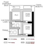
Figure: Cabinet Layout with Multiple Noise Zones. Click to enlarge.
The panel in the Figure has both noisy (digital I/O) and low-noise (analog I/O and input power) conductors. The drive has very noisy (drive output conductors), noisy (drive input power and 120 VAC control), and low-noise (communication and analog) conductors. Where separation cannot be maintained for the low-noise conductors, they are shielded to minimize coupling. Wiring that is designated noisy or very noisy can transverse low noise zones via shielded cable or conduit.
Generally the areas where noise is a problem are within cabinets and long runs of low noise conductors. Within cabinets, the problem is managing the coexistence of very noisy, noisy, and low-noise components in close proximity. Component placement, shielding, and filtering mechanisms will help in the management process. For long, low-noise cable runs (especially communication cables), shielding techniques can improve performance. But there are limits to the maximum achievable distances.
Electrical noise doesn’t have to be cause for concern for management of water and wastewater facilities that are focused on maintaining process integrity, nor the municipalities such facilities serve. A design strategy that focuses on grounding, control panel layout and conductor routing makes the most sense, but municipalities that proactively emphasize such a strategy in its initial input will be in the best position to reap the rewards.
About the Author
Van Wagner is a staff power systems engineer for Schneider Electric's Water and Wastewater Competency Center. He is responsible for power studies, design, investigations, and training in the Midwest region and for strategic accounts. He has 33 years of experience in power systems, 10 of which are with Schneider Electric. Wagner received a master's degree in electrical engineering (’93) from Michigan State University. He is a former chair of IEEE 1346 and is the current chair of the new industrial chapter of the IEEE 1100 "Emerald Book.” Wagner is a registered professional engineer in the state of Michigan.