Don't Let Your Energy Go Up In Smoke
Well-managed VOC abatement systems can help capture process heat that can be reused
- By Tim Golden
- Sep 01, 2007
Competitive pressures and unpredictable energy costs continuously motivate us to examine our
processes for opportunities to increase
quality and productivity, and to
decrease costs. Energy-intensive
processes such as those associated with
the manufacture of a wide variety of
products utilizing water or VOC-based
solvents offer opportunities to reduce
operating costs through heat management
or control. Convection ovens coupled
to thermal oxidizers are a fixture
in many of these manufacturing operations.
Both ovens and oxidizers heat,
circulate, and exhaust large volumes of
air. Without proper design or operation,
large amounts of costly, usable energy
can be carried out the exhaust stack.
For both, the goal of process heat management
is to minimize the volume and
temperature of the exhaust stream.
Heat recovery is the process of utilizing
the excess heat that is generated but
not consumed by a process. This heat
may be directed back to the process as
“primary” heat recovery, utilized by a
related or connected process as “secondary”
recovery, provided to an unrelated
process, or utilized for plant
make-up air heating.
Managing Oxidizer Energy Usage
An oxidizer is an air pollution control
device that operates by heating a
volatile organic compound (VOC) laden
airstream to its destruction temperature,
converting the solvents to carbon
dioxide and water. Typically, the combustion
chamber operates in the range
of 1400 to 1600 degrees Fahrenheit
(760°C to 871°C) to achieve adequate
VOC destruction. In a direct thermal
oxidizer (Figure 1), a burner fires into
the exhaust air stream, heating it to
the combustion temperature. The
clean, hot air stream is exhausted to
atmosphere. In this case, all of the
energy put into the heating of the air
stream, as well as the heat released in
the VOC combustion process, is
exhausted out the stack as waste heat.
Equipment of this design is suitable for
intermittent, low-flow applications
where the capital cost of heat recovery
is large compared to savings in the
operating cost.
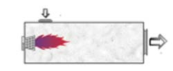
Figure 1. Direct Thermal Oxidizer (No primary heat recovery)
Primary Heat Recovery in the Oxidizer
Most oxidizer designs incorporate a primary
heat recovery system to preheat
the incoming air stream. A heat
exchanger is used to extract heat from
the high-temperature air stream exiting
the combustion chamber and transfer it
to the cooler air stream entering the
combustion chamber. Depending on the
type of heat exchanger employed in the
design, an oxidizer is referred to as “recuperative”
or “regenerative.”
Figure 2. Recuperative Thermal Oxidizer
A recuperative
oxidizer (Figure 2) utilizes an air-toair
heat exchanger to preheat the incoming
air stream. Typical thermal efficiency
of a recuperative heat exchanger is 60
percent to 80 percent.
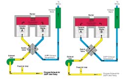
Figure 3. Regenerative Thermal Oxidizer
A regenerative
oxidizer (Figure 3) utilizes multiple beds
of ceramic heat exchange media. One
bed absorbs heat from the outgoing air
stream while another bed releases heat
to the incoming air stream. At regular
intervals, a switching valve reverses the
airflow through the media beds. The
beds cycle between absorbing heat from
the process and releasing heat to the
process. Typical thermal efficiency of a
regenerative heat exchanger is 85 percent
to 97 percent. High efficiency heat
recovery, combined with the exothermic
combustion reaction, creates the
opportunity for the oxidizer to operate
without the need for additional fuel. In
general, the higher the solvent concentration
in the air stream, the lower the
heat exchanger efficiency or supplemental
fuel required to maintain this “selfsustaining”
operation. Regenerative oxidizers
can reach this operating condition
at solvent concentrations as low as
5 percent lower flammability level (LFL).
Secondary Heat Recovery
The oxidizer design and process operating
conditions will determine how much
excess heat is available for secondary
heat recovery. Heat recovery can be
accomplished in two different ways:
Extracting heat from the stack or extracting
heat directly from the combustion
chamber. Dryer exhaust air temperature,
solvent concentration, and heat
exchanger efficiency determine the oxidizer
stack air temperature. As oxidizer
efficiency is increased, the stack temperature
will decrease. Destruction efficiency
requirements determine the combustion
chamber temperature. When concentrations
rise above the minimum
energy required for self-sustaining operation,
excess heat is generated in the combustion
chamber. This excess heat presents
a great opportunity for heat recovery.
Whereas the oxidizer stack temperature
will be 100 to 400 degrees Fahrenheit
(55 to 222°C) above the inlet temperature,
air from the combustion chamber
will be at 1400 to 1600 degrees
Fahrenheit (760°C to 871°C). Depending
on the need, various forms of heat
recovery options are available.

Figures 4, 5, and 6
Direct Air
Direct air heat recovery (Figure 4) is an
arrangement in which heated air from
the oxidizer is ducted directly to the
process. Coupled to a convection dryer,
this air can be utilized as preheated
make-up air. This system is simple and
requires very little auxiliary equipment:
modulating dampers, fans and pressure
control loops. Direct air recovery does
require a large amount of high-temperature
ductwork. This system often
proves impractical when space is limited,
the oxidizer is located a great distance
from the dryer, or the product or
process will be affected by the partially
contaminated air.
Air-to-Air
Heat recovery with an air-to-air heat
exchanger (Figure 5) is similar to direct
air heat recovery. This system should be
considered if products of combustion
from the oxidizer may contaminate the
drying process or if recovered, energy is
used to heat an°Ccupied area. It’s
important to carefully analyze the dryer
operating conditions whenever considering
a blended air heating system. Dryer
air temperature is directly related to the
volume of makeup air. If air volume and
temperature requirements cannot be
balanced, an auxiliary heating system, such as a gas-fired burner, may be
required to supplement the heat recovery
system.
Air-to-Oil
Another recovery method is an air-tooil
heat exchange (Figure 6). The
exhaust air from the oxidizer passes
through a heat exchanger, heating a
thermal oil. This system offers more
operating flexibility for the dryer than
the direct air or air-to-air systems. With
either of the air-based systems, the oven
must take a volume of makeup air that
is proportional to the heat requirements
of that zone. The more heat required,
the more makeup air that zone must
take. This is often contrary to the optimum
operating condition for the oven.
The zones with high evaporation rates,
the early zones of the oven, usually
operate at lower temperatures than the
latter zones that require much lower
exhaust rates. The air-to-oil heat
exchanger is better suited to these
requirements. An oil-to-air heat
exchanger located in the recirculating
air stream of the dryer allows the air
temperature to be controlled independently
from the makeup air volume. The
hot oil circulation system is more compact,
but more complex and expensive
than a ductwork system.
Air-to-Steam
Air-to-steam heat recovery systems are
similar in design and operation to the
air-to-oil system. Hot oil systems can
operate at higher temperatures than steam. Steam offers higher heat transfer
rates. Typically, steam is preferred in a
facility already using steam. Otherwise, a
hot oil circulation system can be used.
Absorption Chiller
A less common heat recovery alternative
is using waste heat to provide
chilled water. Usually, the cost and complexity
of these systems are prohibitively
high when compared to a conventional
chiller system.
Heat Recovery Considerations
It’s important to understand that as the
efficiency of the primary heat recovery
systems in the oxidizer is increased, the
amount of heat available for secondary
recovery decreases. A well-designed primary
heat recovery system may eliminate
the need for any secondary system.
The design goal for any new system
should be to first optimize the primary
heat recovery system. Secondary heat
recovery requires the interconnection of
two separate operating systems. It’s
important to thoroughly analyze the
operating cycles of both the process and
oxidizer through their entire range of
operation. The process provides fuel to
the oxidizer; the oxidizer provides heat to
the process. If supply and demand are
not balanced for all operating conditions,
an auxiliary heat source may be required
at the process. Generally, it’s not recommended
to “overfire” the oxidizer to provide
heat to the process. This analysis
gets even more complex when considering
a tertiary heat recovery system. With
primary and secondary recovery, the
process requiring the heat operates on
the same schedule as the process generating
the heat. The tertiary recovery system
may be providing plant heating or
cooling, or energy to another process
unrelated to the converting line. Supply
and demand are rarely balanced, so tertiary
systems are normally considered
supplemental.
Designing an efficient heat recovery
system is not difficult. Waste heat
sources are matched with potential
users. The appropriate heat transfer and
control system is designed. Determining
the feasibility of a heat recovery system
is difficult. Heat recovery feasibility is a
financial decision. Energy savings must
be balanced against capital, operating,
and maintenance costs over the life of
the system. Accurately quantifying
these variables can be extremely difficult.
A thorough analysis of potential
heat sources and users is necessary.
The skill and experience of the system
designer is critical. Fluctuating utility
prices and changing regulations complicate
payback calculations. The science
and technology of heat recovery is
well-developed. The art lies in the
application.
Checklist for Reducing Energy Consumption
So where do you start an investigation to determine if your existing
or proposed new system(s) are energy-efficient? The investigation
on existing equipment will require a technical person skilled in
measuring or obtaining the pertinent data related to the equipment
evaluation. With new equipment, it should be readily available
in the proposal or obtained during technical reviews of the
planned project.
Some thoughts for an internal evaluation of the energy efficiency of
your existing process:
1. Define the process line’s heat load distribution – where is the
energy going?
a. Heat to substrate and coating
b. Heat to solvent evaporation
c. Heat to make-up air/exhaust
d. Heat available in exhaust sovents via recovery
or combustion
2. How much variation exists in the solvent rate input for the
product range produced? Factor in the amount of production
run time on each product, e.g., a low solvent input rate may
be a high percentage of your production. The line sizing and
your process exhaust are likely based on the higher input rate
product(s) produced.
3. Generate an accurate flow diagram for the process line being
evaluated! Record the entire product input and output conditions
that define your process. Obtain all the associated flow,
temperature, pressure, installed and operating horsepower, etc.
versus the product input data. This data-gathering process
can expend a great deal of time and energy but is essential to
getting results.
4. What are the payback opportunities available related to this discussion?
Some companies have the necessary skills and manpower
within their organizations to evaluate and implement
energy-savings programs. If not, another option to determine if
your process has opportunities to save energy is to contact a
consulting engineering firm or capital equipment manufacturing
company. Many of these companies offer energy and engineering
services to assist you in evaluating your process. Today,
energy costs encompass a significant percent of your total
rising production costs. Accept the challenge, dig in and do
the analysis and implementation work – you and your market
will both benefit.
5. Check with local, state and federal agencies. Oftentimes, funding
tax benefits or low-cost loans are available for projects with
proven energy reduction. |
This article originally appeared in the 09/01/2007 issue of Environmental Protection.
About the Author
Tim Golden is the aftermarket services manager for MEGTEC Systems, a leading manufacturer of air pollution control and industrial drying equipment for the web coating, printing and converting industries. Golden has over 12 years of experience in rebuilds, upgrades, installation, testing and maintenance of air pollution control equipment, industrial drying systems and heat recovery systems to the printing, coating, and related industries. He can be reached by telephone at (920) 337-1459.